
Registered Office: Millom Network Centre, Salthouse Road, Millom , LA18 5AB
© 2017 As-Built Solutions Limited Registered in England and Wales Company Number 2872876

measurement of industrial plant and complex infrastructure

ABSL Metric Images



Rapid Routing benefits
Rapid Routing is a key part of the Hazmap Modeller product, demonstrating that the connectivity and function of pipelines is as vital as the as-built geometrical description of the position and orientation.
It is proving to be a highly cost effective way of producing as-built "CAD friendly" intelligent pipe data.
- Create exactly the amount of 3D data required to accurately define the geometry of the route. There is no need to distil or extract simple positions, orientations and dimensions from redundant 3D data in a scanned point cloud.
- Incredibly it does this with almost no measurement being necessary when compared with conventional photogrammetric systems.
- Positioning is possible from a single image it is ideally suited to dense and cluttered plant areas where having coverage from more than one view
- The method encourages accurate functional description of the piping components being positioned. They are categorised both in generic terms, Valve Bend, Tee etc and optional also user labels Valve-T300.
- The inherent description of inter-component connectivity and geometry reflects the as-built reality in a way that integrates easily with CAD piping software originally intended for green field design work.
Define a starting point and initial direction:
A single point is measured on the pipe to be routed using the Hazmap Measurement tools ( tangent measurements will define the OD of the pipe will be available and used to automatically size the pipe).
The user clicks on the point and define the initial direction of the pipe, in this case north.
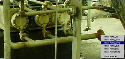

Rapid routing technique
Specify the direction of the next section of pipe
In this case the direction is up.
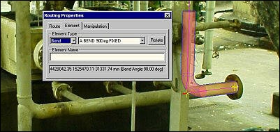
Sizing can be specified or derived from the original measurement. For example the pipe attribute may be used to define a nominal OD and the graphical techniques shown here work with a larger lagged OD.
1
2

The next section of pipe is positioned
3
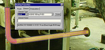
The next section of pipe is positioned, by a click on the centreline of the pipe on the left. This action is actually positioning the bend seen at the lower end of the red section. A 90 deg fixed bend is being used here but a variable angle bend is available.

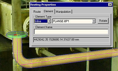
The next element in this case is a flange.
The flange is an inline element, i.e. it does not change the direction of the current pipe section.
A click of the mouse positions the flange constrained to the current section.
4

5
Position the next element
Position th enext element with a single mouse click on the first flange of the assembly seen on the left.
In a few seconds we have successfully defined part of a pipe route including:
- Starting point
- Orientation
- Size
- and first two components, a bend and flange
The route can then be saved or exported to a variety of CAD package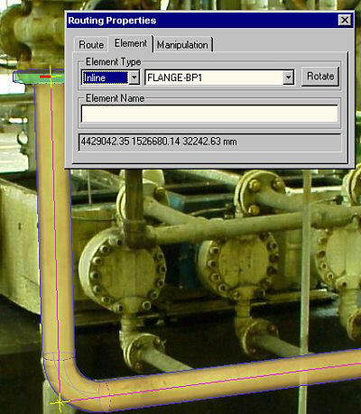 s via user customisable scripts.


